3.2 A-1 STAGE ENGINE
Four engines of 750000 -pound thrust each were selected for a combined thrust of 3 million pounds ( 3000 K ), as a compromise between number of engine systems, and thus complexity on one hand, and flexibility on the other. Flexibility is offered through the possibility of including engine-out capabilities; of using existing smaller systems or designs; and for guidance and packaging considerations.
The propellant combination of liquid oxygen and kerosene type RP-1 fuel was selected for the A-1 engine. The selection was guided by the consideration that high performance is not as critical for first booster stages as it is for upper stages. Both propellants are abundantly available and comparatively inexpensive. The fluids and their combustion products are "docile"; their corrosivity is nil. Both fluids are relatively dense. Liquid propellant rocket engine systems using these propellants are well developed and reliable, and many "off the shelf" components and designs are available for them.
General Engine System Description
The A-1 engine is a single-start, fixed-thrust, gimbaled, bipropellant system. The fuel, RP-1, is also used as the turbopump lubricant and as the engine control system actuating fluid. The major components of the A-1 engine are a regeneratively fuel-cooled, double-pass, tubular-wall thrust chamber with bolt-on injector; a directdrive turbopump consisting of two centrifugal pumps and a single-stage, two-wheel turbine; an uncooled gas generator with dual-ball valve; butterfly main valves; and required controls. The gas generator uses the same propellant combination as the thrust chamber. Table 3-2 presents all necessary operating parameters on which engine component designs will be based for the A-1 engine system.
The A-1 engine system schematic diagram is shown in figure 2-7. This diagram identifies clearly all major engine components and their interconnecting plumbing. For the various
Table 3-2.-750K A-1 Stage Engine Operating Parameters [Sea-level conditions] Engine (turbopump feed): Line pressure drop psi ..... 10 Thrust ..... lb . . . . . . . 750000 Nominal single-firing duration ..... sec. . . . . . . . . 165 Specific impulse sec. . . . . . . 262.4 Oxidizer : Flow rate ..... lb/sec . . . . 1967.7 Density Fuel RP-1: Flow rate ..... lb/sec . . . . 892.3 Density. ..... 50.45 Mixture ratio O/F ..... 2.20 Thrust chamber (tubular wall construction regeneratively cooled by fuel): Thrust ..... lb . . . . . . . 747000 Specific impulse ..... sec. . . . . . . . . 270 Injector end pressure psia ..... 1095 Nozzle stagnation pressure psia ..... 1000 Oxidizer flow rate ..... 1941 Fuel flow rate. lb/sec ..... 827 Mixture ratio O/F ..... 2.35 efficiency Percent ..... 97.5 ..... 5660 efficiency Percent ..... 98 ..... 1.532 Contraction ratio ..... 1.6 Expansion ratio ..... 14 Throat area in ..... 487 L* . in ..... 45 Nozzle contour ..... 80 percent bell Oxidizer side: Injector pressure drop psi ..... 200 Torus dome pressure drop psi ..... 150 Line pressure drop psi ..... 25 Main valve pressure drop psi ..... 35 Pump inlet pressure psia ..... 55 Pump discharge pressure psia ..... 1505 Developed pump head ft ..... 2930 Pump: Flow rate lb/sec ..... 1971 Shaft power bhp ..... 14850 Efficiency Percent ..... 70.7 Shaft speed rpm. ..... 7000 Heat exchanger ..... 3 Fuel side: Injector pressure drop psi ..... 200 Jacket and manifold pressure drop psi ..... 290 Main valve pressure ..... psi ..... 15 Calibration orifice pressure drop psi ..... 110 Pump: Inlet pressure psia ..... 45 Discharge pressure. psia ..... 1720 Developed pump head ..... 4790 Pump: Flow rate ..... lb/sec ..... 892 Shaft power bhp ..... 11790 Efficiency Percent ..... 65.8 Shaft speed rpm ..... 7000 Turbine: Inlet pressure psia ..... 640 Inlet temperature ..... 1400 Pressure ratio ..... 23.7 Gas flow rate ..... 92 Shaft power ..... bhp. . . . . . . 27140 Efficiency Percent ..... 58.2 Shaft speed rpm. ..... 7000 Shaft torque in-lb ..... 20380 Auxiliary drive: Shaft power bhp. ..... 500 Gas generator system: Oxidizer side: Flow rate lb/sec ..... 26.7 Entrance loss psi ..... 25 Line pressure drop psi ..... 25 Control-orifice pressure drop psi ..... 615 Valve pressure drop psi ..... 10 Injector pressure drop psi ..... 120 Fuel side: Flow rate ..... 65.3 Entrance loss psi ..... 25 Line pressure drop psi ..... 25 Control-orifice pressure drop psi ..... 800 Valve pressure drop psi ..... 20 Injector pressure drop psi ..... 140 Gas generator: Mixture ratio ..... O/F ..... 0.408 Injector end pressure psia ..... 710 Combustor pressure drop psi ..... 70 Thrust vector control: Minimum acceleration ..... 1 Maximum velocity deg sec ..... 10 Displacement deg. .....
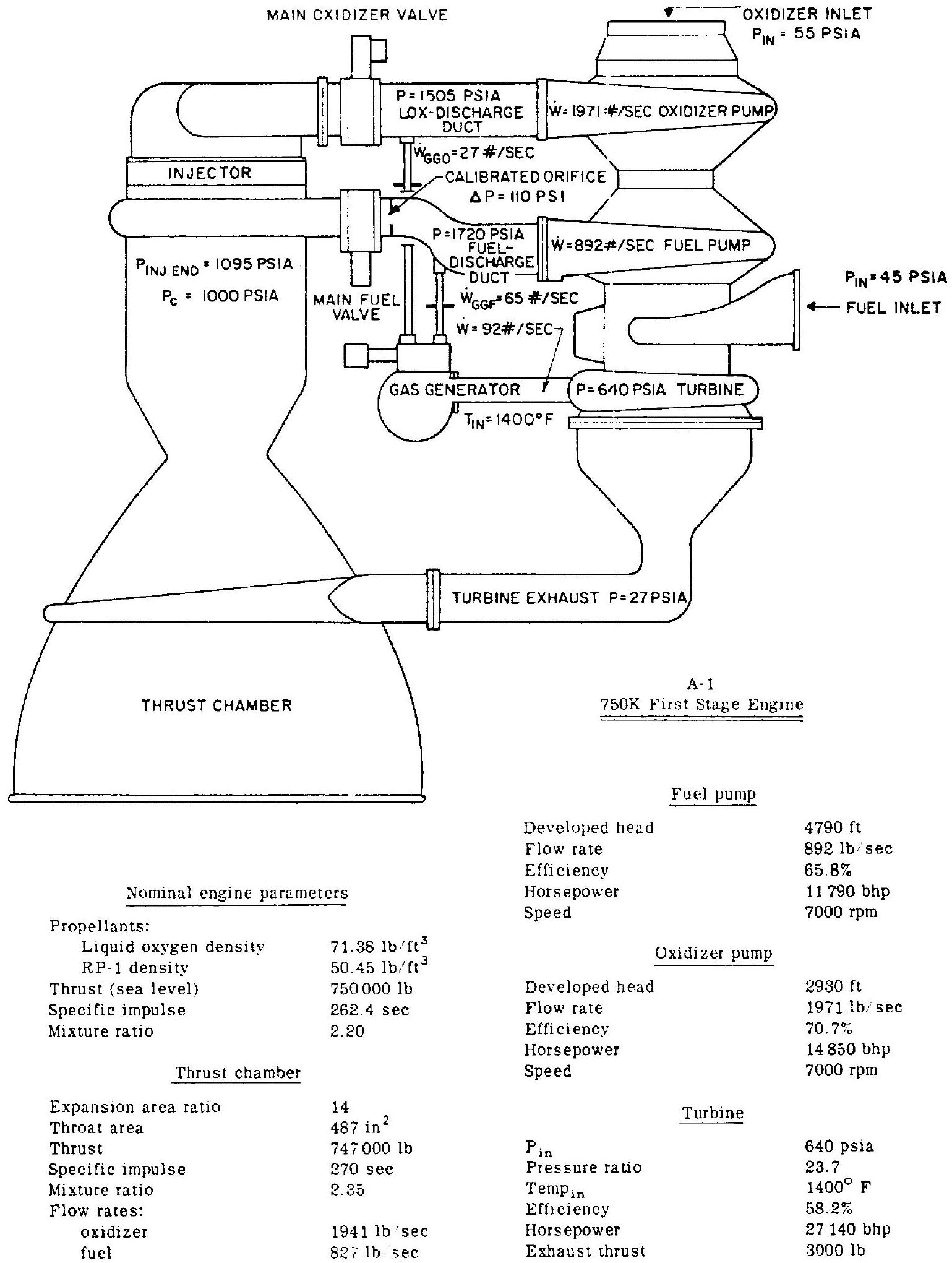 Figure 3-1.-A-1 engine performance diagram.
phases of engine design and development, it has been found useful to work from an "engine performance diagram." This is a combination of the basic engine schematic and the principal performance parameters. The A-1 engine diagram is shown in figure 3-1. It is suggested that the reader prepare his own performance diagrams for the other three stages.
For simplicity of mounting and compactness, the turbopump is attached directly to the thrust chamber. All other components are either mounted on these two assemblies, or are located in the plumbing system between them. This arrangement permits engine gimbaling without pumpdischarge high-pressure propellant-duct flexure. Rather, thrust-vector control is achieved by gimbaling the entire engine. The engine weighs approximately 7500 pounds dry, 7900 pounds wet, and 7830 pounds at burnout. The preliminary design layout of the A-1 engine system and its overall dimensions are shown in figure 3-2.
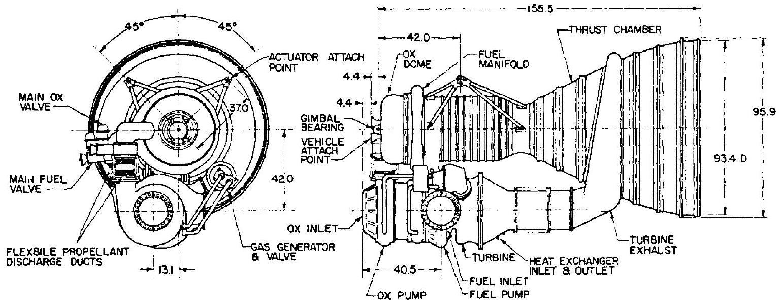 Figure 3-2.-A-1 750 K first stage engine system preliminary layout.
System Operation
The starting method of the A-1 engine is the "main-tank-head start," combined with pressure ladder sequence (figs. 2-7 and 2-8). Propellants are used under vehicle-tank-head pressures to initiate gas generator operation. As the turbopump starts to accelerate, main propellant pressures "bootstrap" the system to mainstage level.
Starting Sequence
After all vehicle launch preparations are completed and the main propellant tanks are pressurized, the gas generator dual sparkplugs are activated upon a given signal and the engine four-way control valve is energized to open. The closing side is vented and fuel pump outlet pressure ( 50 psia from tank head) is admitted to the opening side of the main oxidizer and gas generator valve actuators. The gas generator valves open and admit both propellants to the gas generator combustor, where they are ignited by the spark plugs. At this point, the main oxidizer valve remains closed, since the valve spring prevents opening until substantially higher actuating fuel pressures are developed by the pump later in the sequence.
The low initial gas generator power level is sufficient to start and accelerate the turbopump. This, in turn, increases the propellant pressures available to the gas generator, which is connected upstream of the still closed main valves. As a result, the gas generator-turbine system "bootstraps" itself.
At a predetermined fuel pump outlet pressure (valve spring rate selection), the main oxidizer valve opens. During the oxidizer valve stroke, an integral and mechanically linked igniter fuel sequence valve is actuated. The sequence valve in turn admits fuel pressure to the hypergol igniter cartridge, rupturing its diaphragms. Hypergol (such as triethylaluminum) enters the combustion chamber igniter elements and ignites with the oxidizer just being admitted by the main oxidizer valve. Fuel following the hypergol sustains the igniter flame.
The chamber pressure resulting from igniter combustion is sufficient to actuate the ignition monitor valve. This valve admits fuel pressure to the main fuel valve opening actuator, opening the valve, which is the last step in the sequence. Main fuel enters the combustion chamber; chamber pressure and thrust climb to the rated level.
Cutoff Sequence
Upon receipt of a cutoff signal, the engine four-way control valve is deenergized to close. The opening pressures of all valves vent; the valves close. Turbine power and main chamber pressure decay. While the main propellant tanks vent, all valves are held in their closed position by springs. Note that the gas generator valve and the main oxidizer valve are closed by admitting actuation pressure to their closing port, while the main fuel valve is closed by spring force only. Experience has shown that cutoff precision is largely influenced by turbopump decay characteristics and by cessation of that propellant flow which has the smallest duct volume below the valve, in this case the oxidizer (no cooling jacket). The fast closing valves need some timing, however, from water-hammer considerations.